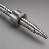
A customer building a vertical lift for battery trays called us after his second screw failed the same way. Under load the 16 mm screw visibly bowed, the axis lost position, and after a few hundred cycles the shaft stayed bent. He had checked the dynamic load rating - 1,380 kgf against a working load of about 400 kgf - and concluded the screw was massively oversized for the job.
His arithmetic was right. He was checking the wrong number.
Load rating and column strength are unrelated
The Ca figure in a catalogue tells you about fatigue life of the ball raceway. It says nothing about whether a long thin shaft will stay straight when you push on the end of it.
Push axially on a slender rod and below a certain force it stays straight. Above it, the rod snaps sideways - not gradually, but suddenly. That threshold is the buckling load, and it has almost nothing to do with the raceway. It depends on the root diameter of the shaft, the distance between supports, and how the ends are held.
Compression only. A screw in pure tension cannot buckle, which is why the same axis flipped upside down sometimes just works.
The formula and the factor that dominates it
Fk = 40720 × (Nf · dr4) / Lt2
Where Fk is the buckling load in kgf, dr is the root diameter of the screw shaft in mm, Lt is the distance between support bearings in mm, and Nf is a factor set by the mounting arrangement (HIWIN Ballscrews Technical Information, section 4.5).
Apply a safety factor to get the permissible load:
Fp = 0.5 × Fk
And Nf by end fixity, from the same source:
| Mounting arrangement | Nf | Relative to fixed-fixed |
|---|---|---|
| Fixed – fixed | 1.0 | 100% |
| Fixed – supported | 0.5 | 50% |
| Supported – supported | 0.25 | 25% |
| Fixed – free | 0.0625 | 6.25% |
Sixteen to one between best and worst, on identical hardware.
Two things in that formula deserve a second look. Root diameter enters to the fourth power - go from 16 mm to 20 mm nominal and the buckling load rises by roughly two and a half times, not 25%. Length enters as a square, and in the denominator: double the span and you keep a quarter of the capacity.
So the three levers are wildly unequal in strength. Changing end fixity is usually free. Increasing diameter is cheap. Shortening the span is often impossible. Work them in that order.
Running the customer's numbers
His lift: 16 mm nominal screw, 5 mm lead, roughly 1,400 mm between bearings, mounted fixed at the gearbox end and free at the top. Root diameter on a 1605 is about 13.8 mm.
With Nf = 0.0625 for fixed-free:
Fk = 40720 × (0.0625 × 13.84) / 14002 ≈ 47 kgf
Permissible load Fp ≈ 23 kgf.
He was applying around 400 kgf. Seventeen times over the limit - of course it bowed. The screw was not defective and the supplier had not cheated him. The column check had simply never been done.
Now change one thing. Add a support bearing at the top so the arrangement becomes fixed-supported, Nf = 0.5:
Fk = 40720 × (0.5 × 13.84) / 14002 ≈ 377 kgf
Eight times better for the cost of one bearing housing. Still not enough for 400 kgf with a safety factor, so he also moved to a 25 mm screw. Root diameter about 21.9 mm:
Fk = 40720 × (0.5 × 21.94) / 14002 ≈ 2390 kgf
Fp around 1,195 kgf against a 400 kgf working load. Comfortable.
Vertical axes are where this bites
Horizontal axes usually escape. The nut pushes and pulls a table that is carried by the rails, and the screw often sees far less sustained compression than you would guess.
Vertical is different, and worse in a specific way people miss. A vertical lift holds load continuously, not just during the move. When the axis is parked with a full load on it, the screw sits in compression indefinitely. Buckling is a stability limit, not a fatigue limit - it does not care how many cycles you have run, only what force is on the shaft right now.
The orientation question is worth asking early: can the screw be arranged so the load pulls rather than pushes? A screw in tension has no column limit to check. Sometimes flipping the drive from bottom-mounted to top-mounted solves the whole problem.
Where the mistakes cluster
Assuming "fixed" means "bolted down firmly". Fixed in this context means a bearing arrangement that resists moment - a proper fixed-side unit with angular contact bearings. A plain deep-groove bearing in a bracket is a simple support, whatever the bolts look like.
Counting Lt as the stroke. It is the distance between the support bearings, which includes the nut length, overtravel and the journal sections. It is always longer than the stroke, and it is the number that gets squared.
Assuming symmetry between compression and tension. Only compression buckles.
Using the nominal diameter instead of the root diameter in the formula. On a 1605 that is the difference between 16 and about 13.8, and raised to the fourth power it is a 1.8× error in your favour - exactly the wrong direction to be wrong in.
Checking buckling but not critical speed, or vice versa. They are separate limits with separate formulas, and a long screw can easily fail one while passing the other.
Before you commit to a design
Send stroke, total shaft length, orientation, intended end fixity, and maximum sustained axial load - especially load held while stationary. The column check takes a minute and it is free. Finding out after the machine is built costs a redesign.
Related reading
- The Relationship Between Ball Screw Preload And Axial Clearance
- How To Select Ball Screw Support Units
- Demystifying Ball Screw Selection
- Ball Screw SFU1605 SFU2005 C7 Flange Nut
Tianjin OuNaiDa runs buckling and critical speed checks as part of every ball screw quotation. Send your stroke, orientation and load data and we will confirm both limits before you order.
Precision Motion Components | Empowering Global Intelligent Manufacturing