How to Measure a Ball Screw Without a Part Number
The screw comes out of the machine after eight years. The nameplate is long gone, the shaft is covered in old grease, and whatever marking it once had has worn off. The machine is down and the buyer needs a replacement quoted today.
We get this enquiry regularly. It is entirely workable - a ball screw can be identified from measurements alone. But the measurements people take first are often not the ones that decide whether the replacement fits.
Here is the order that works.
Step 1: Shaft Outer Diameter
Measure across the thread crests at a section of the shaft that has not been running in the nut - usually near one end. Use a caliper, take three readings at different points, and use the largest.
Why the unworn section: the region the nut has travelled over for eight years will read undersize, and that measurement will send you to the wrong size class.
The result normally lands close to a standard nominal size - 12, 16, 20, 25, 32, 40, 50 mm. A reading of 15.6 mm on a worn screw is a 16 mm screw.
Step 2: Lead
This is the most frequently mismeasured dimension, and the one that causes the most returns.
Lead is the axial distance the nut travels in one full turn of the screw. It is not the same as the distance between adjacent thread crests, which is the pitch. On a single-start screw they are equal. On a multi-start screw they are not.
Reliable method:
- Mark a reference point on the shaft
- Turn the screw exactly 10 full revolutions
- Measure the axial distance the nut moved
- Divide by 10
Ten turns averages out measurement error and, importantly, gives the correct answer on a multi-start screw where counting crests does not.
Standard leads are 4, 5, 10, 16, and 20 mm. Diameter and lead together give you the core designation - a Ø16 screw with 5 mm lead is a 1605.
Step 3: Nut Type and Mounting
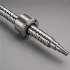
Photograph the nut and measure:
- Flange outer diameter
- Bolt hole count - commonly 4 or 6
- Bolt circle diameter - centre to centre across opposing holes
- Bolt hole diameter
- Flange thickness
- Nut body length and nut body outer diameter
Note whether the flange is round or has a cut-off "D" shape, and whether the nut carries wipers or seals at the ends.
The distinction that matters here: a standard flange nut and a dust-proof nut of the same diameter and lead often share mounting dimensions but differ in body length. If the original was a dust-proof type and the machine works in a dusty environment, replacing it with a standard nut will look correct on the drawing and fail early in service.
Step 4: Shaft Ends - Where Most Replacements Go Wrong
This is the step people skip, and the reason a "correct" replacement arrives and will not mount.
Measure and sketch both ends separately. They are almost always different.
For each end, record:
- Journal diameter - where the bearing seats
- Journal length
- Bearing shoulder diameter and its distance from the end
- Thread specification - diameter and pitch
- Threaded section length
- Keyway dimensions, if present - width, depth, length
- Any snap ring groove position and width
Note which end carries the lock nut thread. That is the fixed end, and it tells us the orientation. If you are also reusing the existing support units, these dimensions have to match them exactly.
A sketch with dimensions written on it beats a paragraph of description every time. It does not need to be a drawing - a clear hand sketch with numbers is genuinely sufficient.
Step 5: Overall Length and Thread Length
Two different numbers, both needed:
- Total shaft length - end to end, including both machined ends
- Threaded length - the ball groove section only
The difference between them is taken up by the two shaft ends. Confirm your effective stroke as well, since it determines whether the thread length is adequate once the nut body and any over-travel allowance are accounted for.
What to Send With an Enquiry
From the enquiries that get quoted accurately the first time, the pattern is consistent:
Photographs
- Full screw laid alongside a tape measure or ruler
- Both shaft ends, close up
- The nut from the side, and from the flange face
- Any visible marking, even partial - a fragment of a part number saves all of the above
Measurements
- Shaft outer diameter
- Lead, measured over 10 turns
- Total length and threaded length
- Nut flange dimensions and bolt pattern
- Both shaft-end sketches
Context
- What the machine is and what it does
- Why the screw is being replaced - normal wear, crash damage, or a recurring failure
- Whether the existing support units are being reused
That last point matters more than it sounds. If the support units stay, the new screw's shaft ends must match them exactly. If they are also being replaced, there is room to optimise the design.
When the Original Was the Wrong Screw
Worth raising, because it comes up.
If a screw has failed repeatedly, or shows heavy wear concentrated in one section, the original specification may have been marginal - insufficient diameter for the unsupported length, wrong accuracy grade for the duty, or a nut type unsuited to the environment.
A replacement that faithfully reproduces a marginal design will fail the same way. If the machine has a history, mention it. Sometimes a diameter increase or a different nut type solves a problem the customer has been living with for years.
Measurement Tolerance in Practice
You do not need metrology-grade equipment. A decent caliper and a steel rule will identify a screw correctly.
What matters is measuring the right features - unworn shaft sections, lead over multiple turns, both ends separately - rather than measuring a few features very precisely.
Send us what you have measured along with photographs. If something does not add up, we will ask before quoting rather than after shipping.
Tianjin OuNaiDa Transmissions Technology Co., Ltd. manufactures ball screws, support units, linear guideways, gears, racks, sprockets, and couplings. Established 2008, with 20 years of manufacturing and 15 years of export experience serving over 300 overseas distributors, to CE and ISO 9001:2015 standards. Screws are machined to customer drawings, and we produce the shaft-end drawing for approval when one is not available.
Precision Motion Components | Empowering Global Intelligent Manufacturing